快换接头的基本原理
Fundamentals of quick-acting couplings
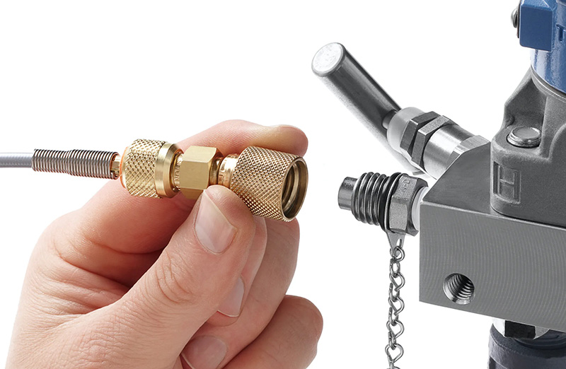
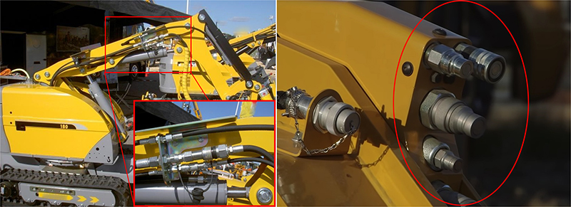
Quick-acting couplings provide a fast, convenient way to repeatedly connect and disconnect fluid lines.
If a hose or tube in a fluid power system will be connected and disconnected more frequently than once a week, then chances are a quick-acting coupling will pay for itself rapidly by improving productivity. Although simple in concept, many quick-acting couplings are precisely engineered for specific fluid applications. Their widespread use over many years has yielded a diverse variety of designs to serve not only specific, but general industrial applications as well. Consequently, uncertainty can arise as to whether a specific deign is best for a given application.
Regardless of the manufacturer, all quick-acting couplings have some elements in common. All have two parts: a plug and a socket. The plug is the male half and the socket is the female half. When connected properly, these parts seal and lock the joint effectively to contain internal pressures and resist any tensile forces that tend to pull the joint apart. The parts are easily disconnected without tools by disengaging a locking mechanism and separating parts.
Where they're used
The more frequently hoses must be connected and disconnected, the more valuable quick-acting couplings become. They also become more critical as machine productivity increases.
One common application is in assembly workstations, where a worker may have to rapidly switch from impact wrench to drill to riveter. With one quick-acting coupling half on every tool and the mating half on the air line, tool changing is accomplished in seconds. Without the couplings, separate air lines would be needed for each tool; the mass of tools and lines would clutter the workstation and could slow down production.
On hydraulic test stands, quick-acting couplings eliminate bottlenecks by slashing the time required to test each assembly. Just a quick push/pull, and the assembly is ready to test. In contrast, testing time would skyrocket if technicians had to tap into systems using fittings and a wrench for each test procedure.
Valve arrangements
Among the many different designs of quick-acting couplings, either of tow types are used for an application. Unvalved types have the advantage of low pressure loss through the coupling, but make no provision to prevent fluid from escaping once the coupling is disconnected. However, if pressure drop in the system must be held to a minimum, and fluid draining from disconnected hoses can be tolerated, unvalved couplings would likely be a designer's first choice.
Obviously, a coupling that does not leak when disconnected would be preferred for probably all applications - all other factors being equal. Incorporating a shutoff valve into one or both halves of the coupling allows fluid to flow through the coupling only when both halves are connected. When the coupling is disconnected, a mechanical link between the coupling halves is broken and causes the valve to close, blocking flow.
When only one coupling half is valved, it usually is located on the source (upstream) end of the joint. Pneumatic systems generally employ this setup: the valved coupling half prevents air loss from the system while the joint is disconnected, the unvalved coupling half allowed downstream air to bleed off.
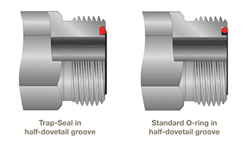
In hydraulic applications, both coupling halves often are valved. This practice not only minimizes fluid leakage, but also limits the amount of air, dirt, and water that can enter the system. When a coupling is disconnected, air can become trapped between valves and enter the system when the joint is reconnected. So if the hydraulic system cannot tolerate air inclusion, special provisions may be necessary to exclude air. To address these concerns, many manufacturers now offer flat-faced couplings that reduce fluid spillage to a drop or less every time the coupling is disconnected. Futhermore, mating surfaces of each coupling half are flush when the coupling is disconnected. This minimizes air ingression and wiping the mating surfaces clean before reconnecting them.
Valve considerations
While these valved designs offer the convenience of controlled fluid loss, there are tradeoffs. First of all, valved couplings can generate a significantly higher pressure drop than unvalved designs. The amount of this loss depends on the coupling size and design. Pressure drop can be reduced somewhat by oversizing the coupling. There also may be some deviation in pressure drop from one coupling design to another. If pressure drop is a concern, be sure to check manufacturer's literature for appropriate data.
Other drawbacks to valved couplings include larger size and higher cost. The cost differential will vary according to size and individual design. Generally, couplings designed for low pressure drop, no fluid leakage, and no air entrapment carry a higher price tag. However, manufacturers point out that the price differential is offset by higher productivity gained by not having to clean up fluid spills.
Coupling types
There are over a dozen common designs of quick-acting couplings. This article covers the six most popular locking mechanisms for fluid power applications.

Figure 1. Ball-lock couplings are the most popular quick-acting coupling in use today and are offered by many manufacturers.
Ball-lock, Figure 1, is the most common design and has the widest range of applications. A group of balls is positioned in holes located around the ID of the socket body. These holes normally are tapered or stepped to reduce their diameter at the socket body ID, so the balls do not fall into the cavity vacated by the plug when the coupling is disconnected.
A spring-loaded sleeve around the socket body's OD forces balls toward the socket body ID. To connect the plug, the sleeve is pushed back, which opens clearance so the balls are free to move outward. Once the plug is in place, releasing the sleeve forces the balls inward against a locking groove on the OD of the plug. To disconnect, pushing the sleeve back provides the balls with clearance to move outward and allow the plug to be removed.

Figure 2. Roller-lock coupling design positions rollers circumferentially around the ID of the socket to grip the plug.
Roller-lock couplings, Figure 2, use locking rollers or pins spaced end-to-end in grooves or slots around the socket's ID. As the plug is inserted, a ramp on the plug OD pushes the rollers outward. Once the plug is inserted the prescribed distance, the rollers slip into a retention groove on the plug's OD. Retracting the locking sleeve, which allows the ramp on the plug OD to move the rollers outward, releases the plug.

Figure 3. Pin-lock couplings use pins arranged in a truncated-cone formation to grip and hold the plug in the socket.
Pin-lock couplings, Figure 3, allow push-to-connect joining using only one hand because the outer sleeve does not need to be retracted to make a connection. In this design, pins are mounted around the socket body ID in a truncated-cone-shaped formation. Pushing the plug into the socket moves pins back and outward, due to a ramp on the plug. Shear across pins locks the plug into the socket. Retracting the springloaded sleeve, which forces the pins back out of the locking groove, releases the plug from the socket.

Figure 4. Flat-faced couplings can virtually eliminate spillage by limiting leakage to a drop of fluid or less upon disconnection. The flat mating surfaces are also easy to keep clean, which prevents contaminating hydraulic fluid upon reconnection.
Flat-face, no-spill couplings, Figure 4, have a poppet-style shutoff valve on each mating half. Most limit leakage during uncoupling to only a film of oil on the coupling's mating surfaces and prevent air ingression during coupling. They are also designed for minimum flow restriction, which minimizes pressure drop during equipment operation.

Figure 5. A twist of the sleeve secures the plug once it has been inserted into the socket of the bayonet-type coupling.
Bayonet couplings, Figure 5, rely on the familiar twist locking arrangement and are widely used in a variety of applications, especially in plastic couplings for lighter-duty pneumatic equipment. To join the couplings halves, lugs on the OD of the plug engage slots in the socket sleeve as the plug is pushed into the socket. A quick turn locks the lugs into position. Turning the plug in the opposite direction allows the halves to be pulled apart.

Figure 6. Ring-lock couplings secure by pushing plug into socket; they disconnect by rotating the socket's outer sleeve.
Ring-lock couplings, Figure 6, use a split ring seated in a groove and slot in the socket.Pushing the plug into position causes a ramp on the plug to spread the ring apart at the split until the ring snaps closed behind a retention shoulder on the plug. Rotating an external sleeve expands the ring, thus releasing it from the retention shoulder so the halves can be pulled apart. This design provides maximum flow in a small envelope for normal shop air applications. A variation of this design uses jaws instead of a split ring to lock the parts together.

Figure 7. Folding back the levers on the cam-lock coupling secures the socket to the plug.
Cam-lock couplings, Figure 7, lock the socket to the plug when two external levers are folded back against the sides of the socket. These are most common in larger sizes and generally require more spaces than comparable couplings of the same size. Moreover, the locking mechanism can wear if lines are connected or disconnected frequently, which can allow leakage.

Figure 8. Multi-tube connectors quickly connect many lines of tubing in a specific orientation.
Multi-tube connectors, Figure 8, are the fluid equivalent to electrical Cannon-style connectors. They quickly and easily connect or disconnect several tubing lines, while maintaining a correct line orientation and discrete flow paths during reconnection.
Coupling selection
Before selecting a coupling, questions must be answered regarding its expected performance. These questions focus not only on the coupling, but the fluid medium as well. For example, what fluid will flow through the coupling? Characteristics of the fluid - viscosity, corrosivity, etc. - will influence the type of coupling that should be used.
Other questions concerning the fluid deal with temperature (high, low, or wide variation), pressure, and flow rate.
Knowing details on the fluid, questions must be answered about the coupling's construction. How often will the coupling be connected and disconnected? What type and diameter of hose or tubing will be used to contain the fluid? Will the coupling or hose be subjected to abuse such as impact from falling objects, severe vibration, or contamination from the environment?
Once these questions have been answered, a preliminary selection of coupling type can be made: one, two, or no shutoff valves, and the type of connect/disconnect mechanism. Keep in mind that one style may offer the greatest convenience in service, but a different model's lower pressure loss may be more desirable for the application.
Materials of construction are another consideration. A wide variety of O-ring and seal materials - elastomers, PTFE, etc. - are available to accommodate most any type of fluid at a wide range of temperatures. Material chosen for the plug and socket also is important. Steel, stainless steal, brass, and aluminum are common. In addition, many parts are made from carbon steel and plated with a corrosion-resistant metal to keep material costs down.
Plastic may be used for many applications if pressure, temperature, and chemical environment permit. Keep in mind that plastic couplings may contain internal metal components that could be corroded by certain types of hydraulic fluid.
Pressure rating relates to values that provide optimum service life and maximum pressure that can be tolerated without failure. Literature should include data for determining pressure drop through the coupling at expected flows and pressures. Many of these calculations are based on flow of water at 60° F.
Keep in mind that pressure drop for oil will be higher because of its higher viscosity. Calculations for air are more complex because a gas's density varies widely with its pressure and temperature. A rule of thumb for air to estimate maximum air flow at 100 psig inlet and 5-psi pressure drop is to multiply flow coefficient of the coupling by 25. Often, literature contains more detailed data on maximum air flow at prescribed inlet pressures and pressure drop. Therefore, precise valves for pressure drop for specific couplings should be obtained from the manufacturer.
Also be aware that couplings may be subjected to pressures well above the maximum operating pressure. Sudden shifting of valves or abrupt application of heavy loads can cause system pressure to quickly rise and fall within milliseconds. These pressure spikes often go undetected in a system, but still can damage seals and locking elements of the coupling. Ultimately, then, the coupling would develop leaks, become difficult to disconnect or reconnect, or any combination of these. To prevent these problems from occurring, select a coupling with a pressure rating substantially higher than the anticipated maximum operating pressure.
Depending on the application, the coupling may be subjected to vibration or relative rotation between the mating halves while pressurized. In most cases, these conditions will shorten the expected life of the coupling by causing leakage or difficulties in connecting or disconnecting. Therefore, check with the manufacturer to determine if the coupling will tolerate these conditions.
A few words on substitution
The various designs of quick-acting couplings available differ not only in how the two halves connect to each other, but also in the valve arrangement to prevent fluid from escaping while the coupling is disconnected. Several designs are fairly standard and may be interchangeable from one manufacturer to another.
These standardized couplings are based on designs for which patents expired year ago. Still, some manufacturers warn against interchanging standard designs between manufacturer because the loose tolerances of one product line may cause problems if it is mated with another product requiring tighter tolerances. The couplings may match based on nominal size but they may not mate or operate properly together.
版权声明:本文为原创文章,版权归donstudio所有,欢迎分享本文,转载请保留出处!