Arduino Programming Basic - Input and Outpput
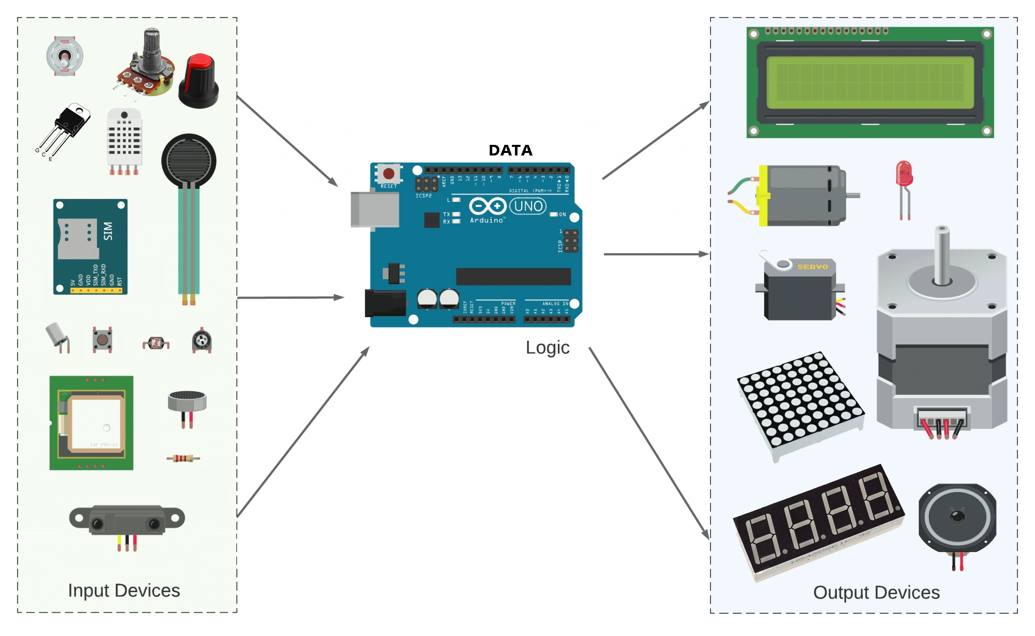
The pins on the Arduino can be configured as either inputs or outputs. This document explains the functioning of the pins in those modes. While the title of this document refers to digital pins, it is important to note that vast majority of Arduino (Atmega) analog pins, may be configured, and used, in exactly the same manner as digital pins.
Properties of Pins Configured as INPUT
Arduino (Atmega) pins default to inputs, so they don't need to be explicitly declared as inputs with pinMode() when you're using them as inputs. Pins configured this way are said to be in a high-impedance state. Input pins make extremely small demands on the circuit that they are sampling, equivalent to a series resistor of 100 megohm in front of the pin. This means that it takes very little current to move the input pin from one state to another, and can make the pins useful for such tasks as implementing a capacitive touch sensor, reading an LED as a photodiode, or reading an analog sensor with a scheme such as RCTime.
This also means however, that pins configured as pinMode(pin, INPUT) with nothing connected to them, or with wires connected to them that are not connected to other circuits, will report seemingly random changes in pin state, picking up electrical noise from the environment, or capacitively coupling the state of a nearby pin.
Pullup Resistors with pins configured as INPUT
Often it is useful to steer an input pin to a known state if no input is present. This can be done by adding a pullup resistor (to +5V), or a pulldown resistor (resistor to ground) on the input. A 10K resistor is a good value for a pullup or pulldown resistor.
Properties of Pins Configured as INPUT_PULLUP
There are 20K pullup resistors built into the Atmega chip that can be accessed from software. These built-in pullup resistors are accessed by setting the pinMode() as INPUT_PULLUP. This effectively inverts the behavior of the INPUT mode, where HIGH means the sensor is off, and LOW means the sensor is on.
The value of this pullup depends on the microcontroller used. On most AVR-based boards, the value is guaranteed to be between 20kΩ and 50kΩ. On the Arduino Due, it is between 50kΩ and 150kΩ. For the exact value, consult the datasheet of the microcontroller on your board.
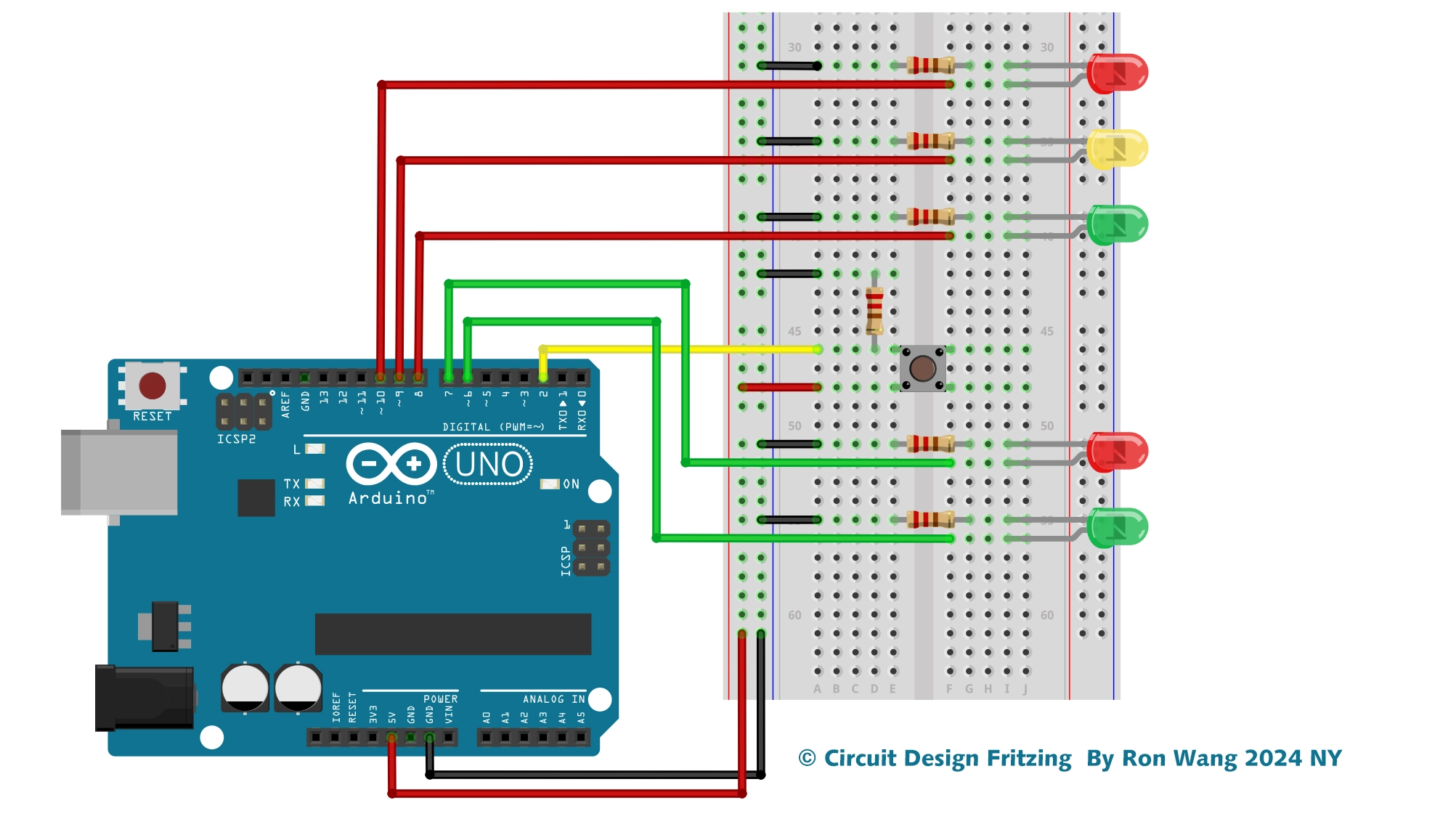
When connecting a sensor to a pin configured with INPUT_PULLUP, the other end should be connected to ground. In the case of a simple switch, this causes the pin to read HIGH when the switch is open, and LOW when the switch is pressed.
The pullup resistors provide enough current to dimly light an LED connected to a pin that has been configured as an input. If LEDs in a project seem to be working, but very dimly, this is likely what is going on.
The pullup resistors are controlled by the same registers (internal chip memory locations) that control whether a pin is HIGH or LOW. Consequently, a pin that is configured to have pullup resistors turned on when the pin is an INPUT, will have the pin configured as HIGH if the pin is then switched to an OUTPUT with pinMode(). This works in the other direction as well, and an output pin that is left in a HIGH state will have the pullup resistors set if switched to an input with pinMode().
Prior to Arduino 1.0.1, it was possible to configure the internal pull-ups in the following manner:
pinMode(pin, INPUT);           // set pin to input
digitalWrite(pin, HIGH);       // turn on pullup resistors
NOTE: Digital pin 13 is harder to use as a digital input than the other digital pins because it has an LED and resistor attached to it that's soldered to the board on most boards. If you enable its internal 20k pull-up resistor, it will hang at around 1.7V instead of the expected 5V because the onboard LED and series resistor pull the voltage level down, meaning it always returns LOW. If you must use pin 13 as a digital input, set its pinMode() to INPUT and use an external pull down resistor.
Properties of Pins Configured as OUTPUT
Pins configured as OUTPUT with pinMode() are said to be in a low-impedance state. This means that they can provide a substantial amount of current to other circuits. Atmega pins can source (provide positive current) or sink (provide negative current) up to 40 mA (milliamps) of current to other devices/circuits. This is enough current to brightly light up an LED (don't forget the series resistor), or run many sensors, for example, but not enough current to run most relays, solenoids, or motors.
Short circuits on Arduino pins, or attempting to run high current devices from them, can damage or destroy the output transistors in the pin, or damage the entire Atmega chip. Often this will result in a "dead" pin in the microcontroller but the remaining chip will still function adequately. For this reason it is a good idea to connect OUTPUT pins to other devices with 470Ω or 1k resistors, unless maximum current draw from the pins is required for a particular application.
数字信号输出 3-3
int outPin = 4;
void setup()
{
  pinMode(outPin, OUTPUT);
  Serial.begin(9600);
  Serial.println("Enter 1 or 0");
}
void loop()
{
  char ch = Serial.read();
  if (ch == '1')
  {
    digitalWrite(outPin,HIGH);
  }
   else if(ch == '0')
   {
    digitalWrite(outPin,LOW);
   }
}
数字输入 3-4
const int inputPin = 5;
void setup()
{
pinMode(inputPin, INPUT);
digitalWrite(inputPin,HIGH);
Serial.begin(9600);
}
void loop()
{
int reading = digitalRead(inputPin);
Serial.println(reading);
delay(1000);
}
数字输入 3-5
const int inputPin = 5;
const int ledPin = 13;
int ledValue = LOW;
void setup()
{
pinMode(inputPin, INPUT);
digitalWrite(inputPin,HIGH);
pinMode(ledPin, OUTPUT);
}
void loop()
{
if (digitalRead(inputPin) == LOW)
{
ledValue = ! ledValue;
digitalWrite(ledPin, ledValue);
}
}
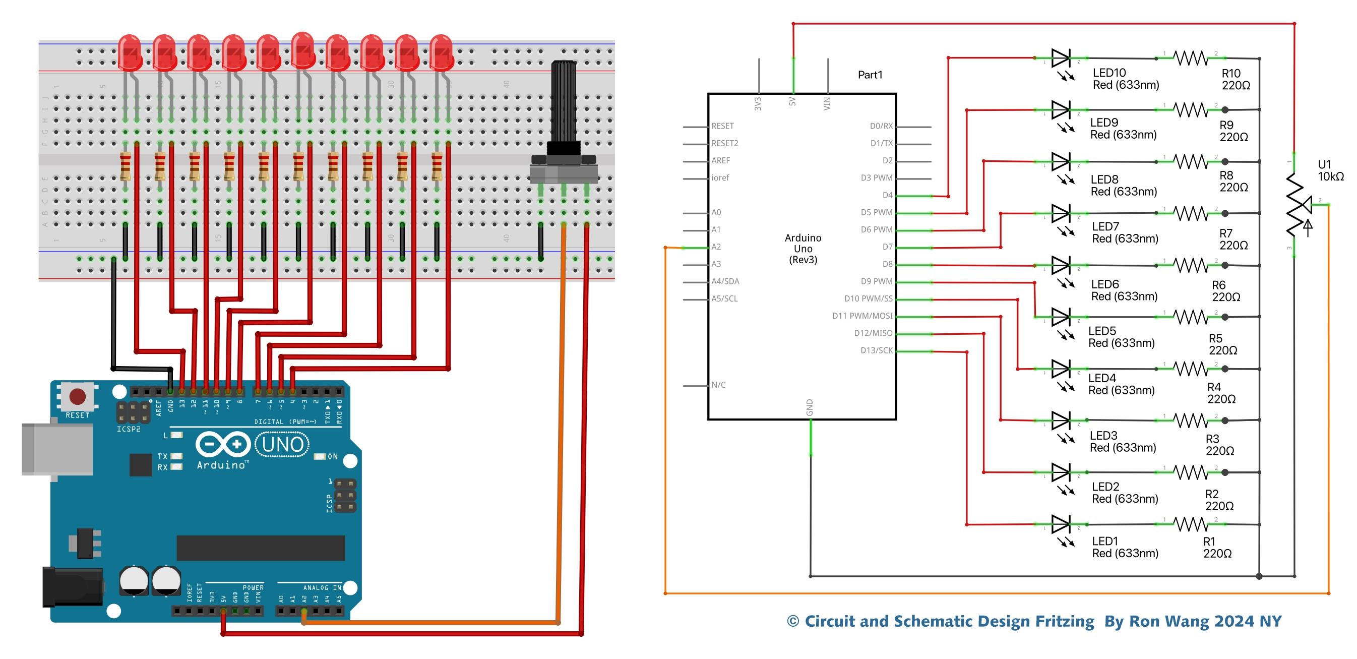
模拟输出 3-6
const int outputPin = 3;
void setup()
{
pinMode(outputPin, OUTPUT);
Serial.begin(9600);
Serial.println("Enter Volts 0 to 5");
}
void loop()
{
if (Serial.available() > 0)
{
float volts = Serial.parseFloat();
int pwmValue = volts * 255.0 / 5.0;
analogWrite(outputPin, pwmValue);
}
}
模拟输出 3-7
const int analogPin = 0;
void setup()
{
Serial.begin(9600);
}
void loop()
{
int reading = analogRead(analogPin);
float voltage = reading / 204.6;
Serial.print("Reading=");
Serial.print(reading);
Serial.print("\t\tVolts=");
Serial.println(voltage);
delay(500);
} 版权声明:本文为原创文章,版权归donstudio所有,欢迎分享本文,转载请保留出处!


